![]() Back
Back
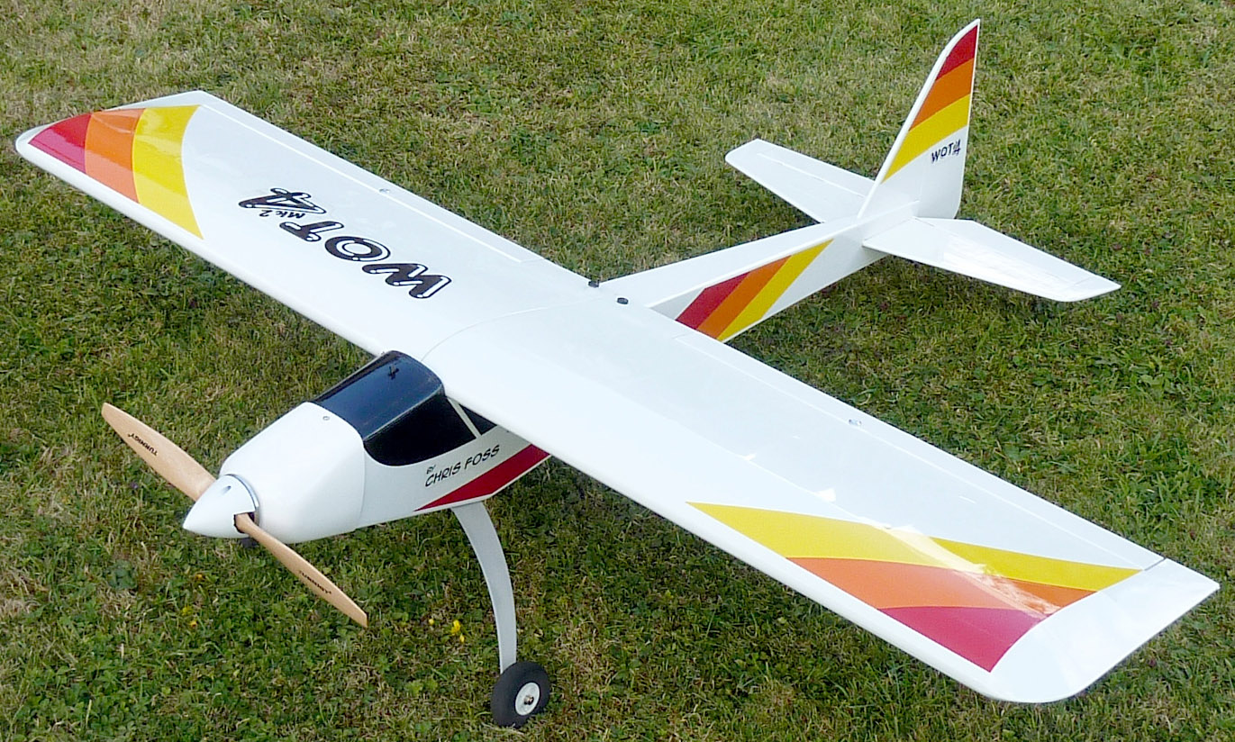
Wot4 mk2 build
notes
‘Breathes there the modeller [man] with soul so dead, Who never to
himself hath said… let’s
modify it’. Apologies to Walter Scott, ‘The Lay of the Last
Minstrel’. Original pastiche from ‘Pylonius’ (Len Ranson of
Hornchurch MC) in his ‘Model Aircraft’ magazine column ‘Topical
Twists’.
This is my second Wot4 Mk2 ARTF. The first met a nasty end due to pilot error. Mostly it went together with no trouble so I’ll only comment on the things that were less than perfect and things that I did differently. Note that there is quite a lot of work involved in converting this model to electric power. I painted bare wood with Eze-kote where I wanted velcro hook strips to stick. I put in some powerful Tower Pro MG958 digital servos and a Propdrive 4248 motor up front. This produces up to 1300W on 5S so is more than powerful enough on 4S using a 14 x 8, or perhaps 13 x 8, propellor. When will they change prop sizes slightly so we can use rounded metric dimensions?
Things I didn’t like.
1 Rudder linkage. I couldn’t see the point of pull-pull rudder linkages on this modest sized model with a modest rudder. Making up the wires and adjusting the connections are a real pain. I decided to use SLEC snakes for rudder and elevators, about which more later. Doing that made me realise that there isn't enough room on the rear fuselage for two rods, which explains the wires.
2 Split elevator. Assembling this is prone to error. The connecting rod has to be glued into the two elevator halves with epoxy at the same time as pushing them onto the hinges. It is tricky to do this without glue going where it shouldn’t.
3 Motor firewall T-nuts. On the first model, one of the M4 T-nuts was poorly threaded. So check and clean the thread with a tap if needed. This time they were fine.
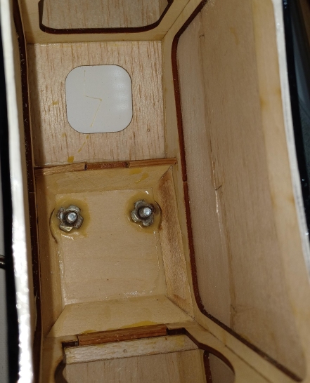
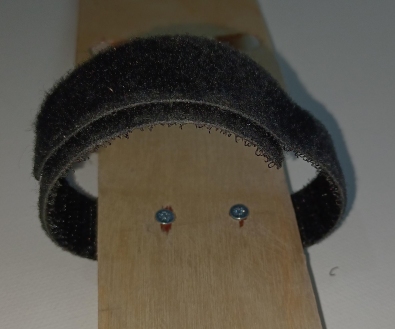
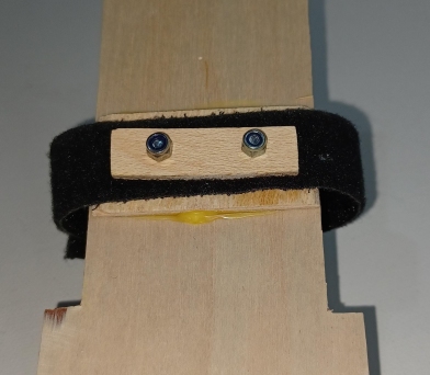
4 Electric conversion kit. For the first model I looked at the details of it and thought, ‘I already have most of this’. So I made a motor mounting plate out of 2.5mm aluminium. I fitted some spacers and M4 screws to suit the motor length. I certainly didn’t like the picture of the battery mount. I did a rough Centre of Gravity check with the 4S 5Ah lipo that I will be using and found it needed to be well forward. So I glued a ply battery plate onto the first three formers with added obeche to increase the stiffness and the glue area. I arranged it so it sloped up to the front making battery insertion easier. I put velcro on the front area and screwed on a velcro battery strap for extra security. The plate is long enough to move the battery to get the correct centre of gravity. I also cut away some of the second bulkhead and strengthened it with obeche. The pictures below show the battery plate and the two front bays. I bought a 57 mm white plastic spinner.
All photos Peter Scott
Motor mounting plate
5 Film. Before cutting the film out of the fuselage servo
rod slots, wing servo holes and wing servo wire holes, I went round
the edges with a film iron. The film was not strongly glued down on
the sheet and might pull away with time. I was a bit concerned that a
single warm air outlet would not be enough for cooling. When I fitted
the cowl I saw that air from the motor could come out through the
side gaps. The new cowl is an excellent glass fibre
one.
Snakes
Unsupported snakes would be
too floppy for proper control. I had to add a light wood strut to
which to fix them, as shown below. That added another step, namely to
find a way of fixing the strut inside the fuselage. There is no plan
to show where the formers are, so I explored using an obeche stick
until I felt an obstruction. I measured the position with the stick
and cut a piece out of the fuselage underside. Its centre is 253 mm
from the back.
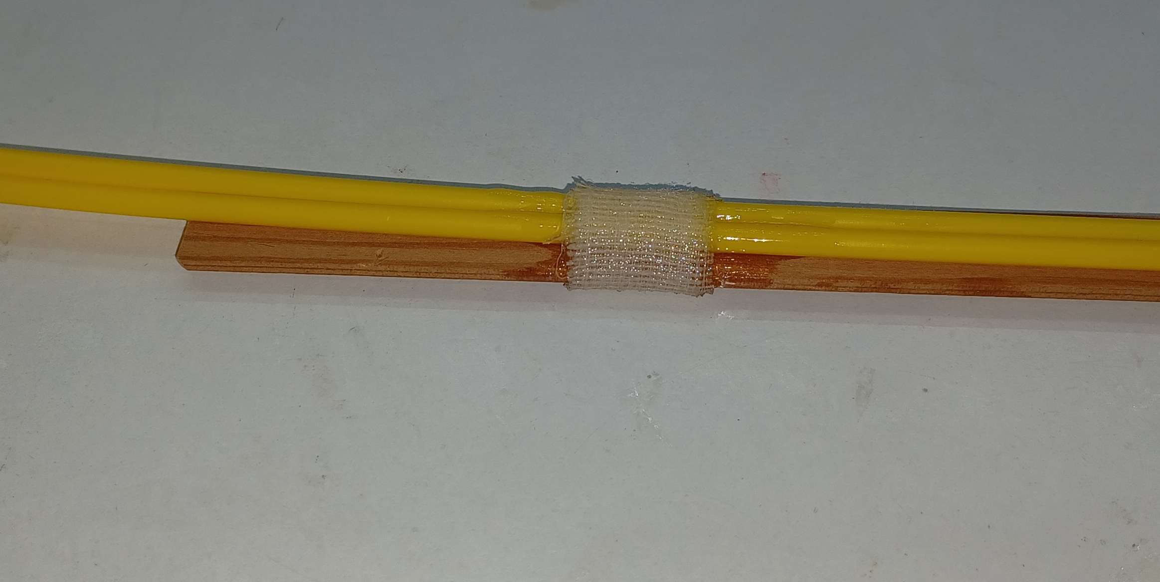 Epoxy and bandage
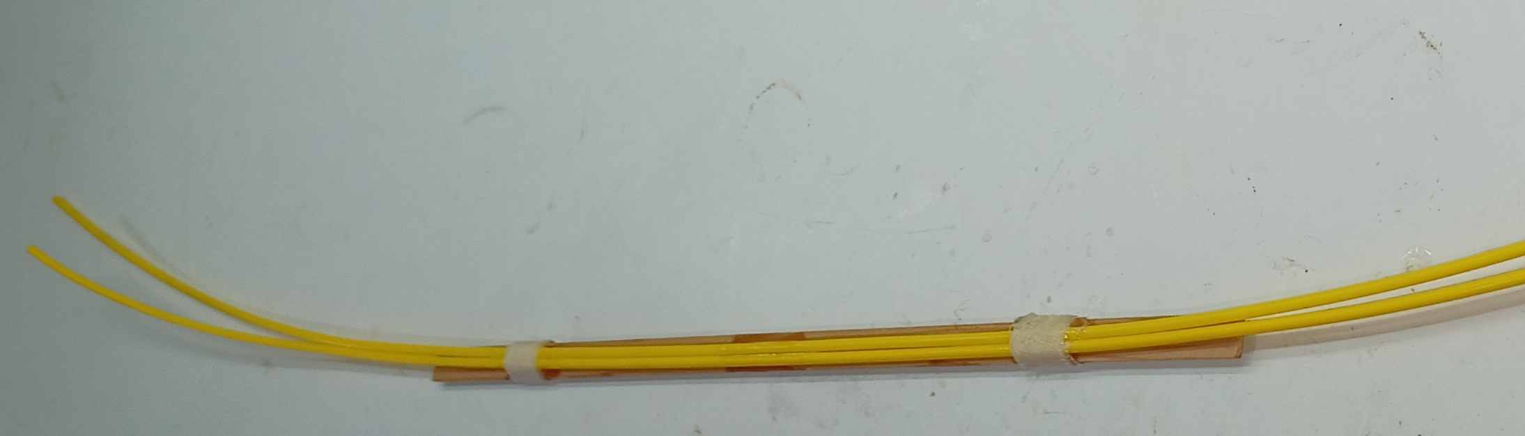
I glued a cross piece to the former to bring the strut up to right level, then fixed the snakes to the strut with plenty of over hang at the back. I pushed the inners through from back to front to allow me to guide the snakes through the rear slots. I put the servos temporarily into place, and after a few dry tries I glued the strut in place on both the servo and rear formers. After trimming the snakes and gluing the underside piece back into place, I was very pleased with the result. Much better than wires and a thick rod. If I build a fuselage from the kit version I can install the snakes even more easily, probably on the fuselage sides.
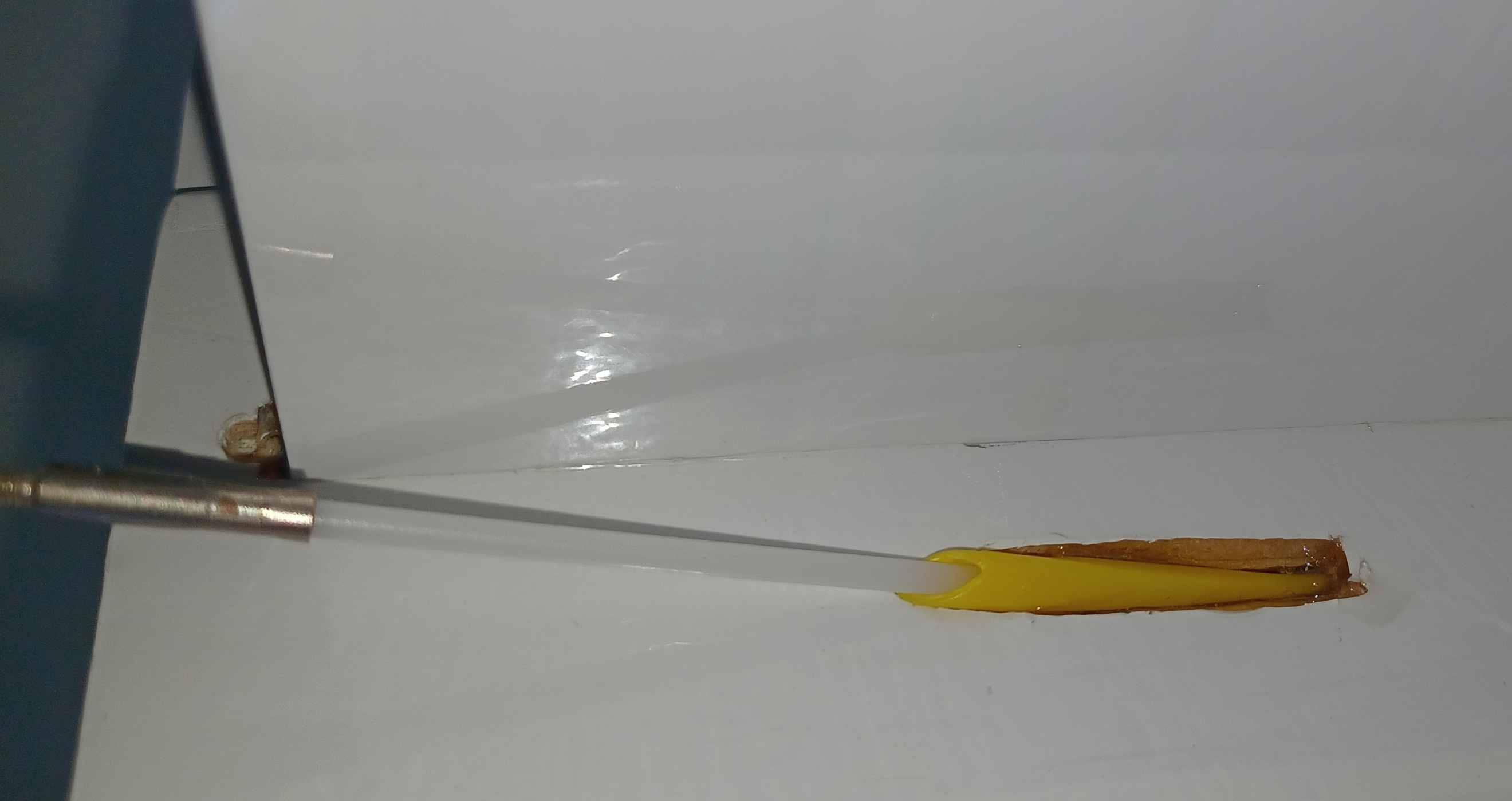
The outlet slots at the back needed enlarging and reshaping to allow the snakes to emerge aligned correctly - all easily done.
Balancing
I now use Nano-tech 4S 5Ah batteries for larger models. When moved
well forward, the model balances in the correct place.
Other
changes
The wheels are a bit small for a grass runway,
so I replaced them with 70 mm ones. I might use nylon M5 screws to
hold the undercarriage on. These will act as weak links in case of a
very heavy landing. The problem is that if they break I won’t be
able to get the stubs out. So I have cut holes through the battery
plate to allow an extraction tool to screw on to the ends of the
nylon bolts. I can then wind them downwards out of the underside.
Radio gear
I like FrSky kit and decided to use the dual frequency, Tandem 2.4 GHz and 900 MHz system for the
first time on this model. The TD R12 receiver has three aerials, a T
shaped one for 900 and two simple wires for 2.4. I used strips of
hook velcro for the aerials in suitable places on the wood of the
fuselage. Then I stuck loop velcro onto neoprene tubes and attached
them for the wire aerials and on the 900 aerial.
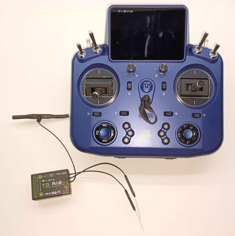
Tandem photos Peter Scott
Channels and initial low rate throws:
1 Throttle
2 Aileron R 9 mm
3 Elevator 15 mm
4 Rudder 45 mm
5 Aileron L 9 mm
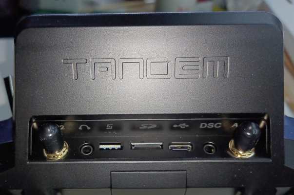
I fitted a switch for the separate receiver battery, for which I found room where the throttle servo would go in a noisebox. This gives extra safety so I can land under control if the lipo suddenly runs down, not that it should with telemetry. For normal use the internal Tx aerials give excellent range. The photo below shows the sockets under the rear of the screen. I will cover the socket holes with a strip of tape in case of a heavy rain shower. The two things with a black covers are SMA screw-type aerial bases. You can buy additional external aerials that screw on and extend the range dramatically, far beyond visible range. Clearly these are for FPV drone users only.
Neuron ESC
I used a FrSky 60S Neuron S ESC. Not
only is it very compact, but it has a wide range of telemetry built
in such as current, rpm, battery voltage, mAh used and ESC
temperature, the first two of which allow optimising the propellor.
Data
All up weight without the battery
was 2150 g. The battery weighed 504 g so total flying weight was 2654
g. The wing area is about 35 dm2 excluding the area over
the fuselage. This makes the wing loading about 76 g/dm2.
Flying
This Wot4 is less agile than an
Acrowot, probably due to its greater weight. I quite quickly
increased the throws that I had set for low rate. After a few more
sessions I switched to using full rate. Even so manoeuvres need to be
planned as the response is not instant unless at high speed, but that
is good for developing my flying skill. Like the Acrowot, the Wot4
can be difficult to stall but when it does it behaves well and does
not drop a wing.
![]() Back
Back
Peter Scott © 2019
Last edit 14 May 2025